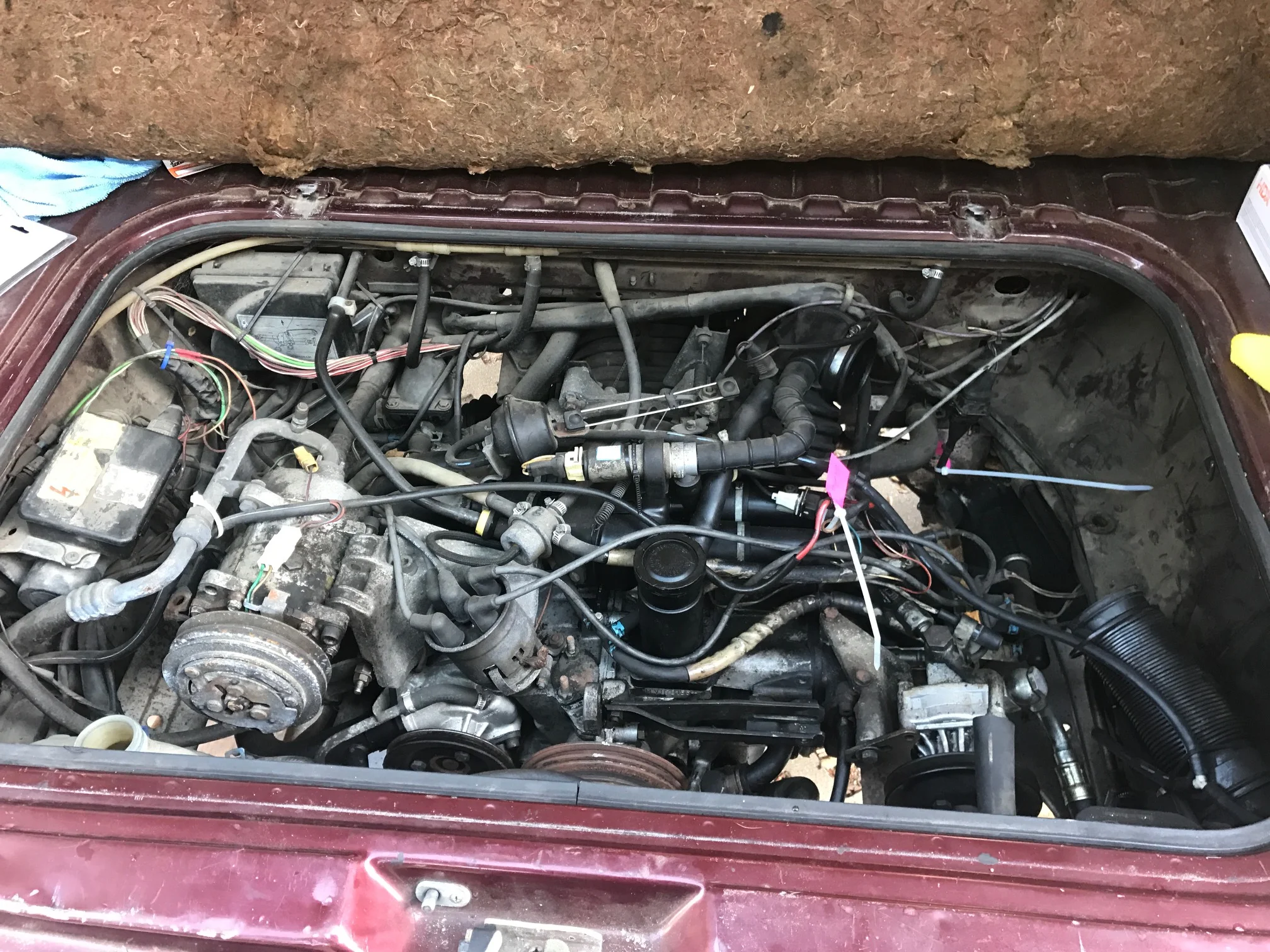
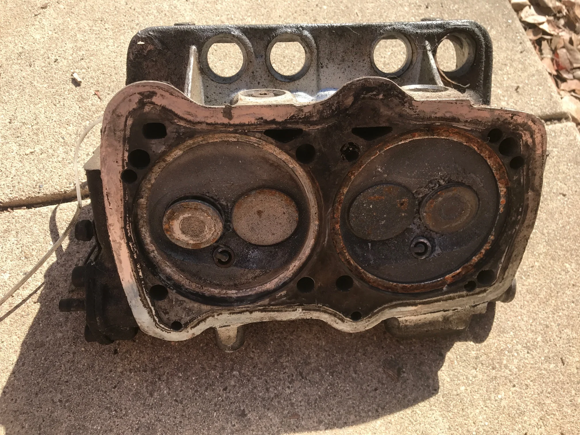
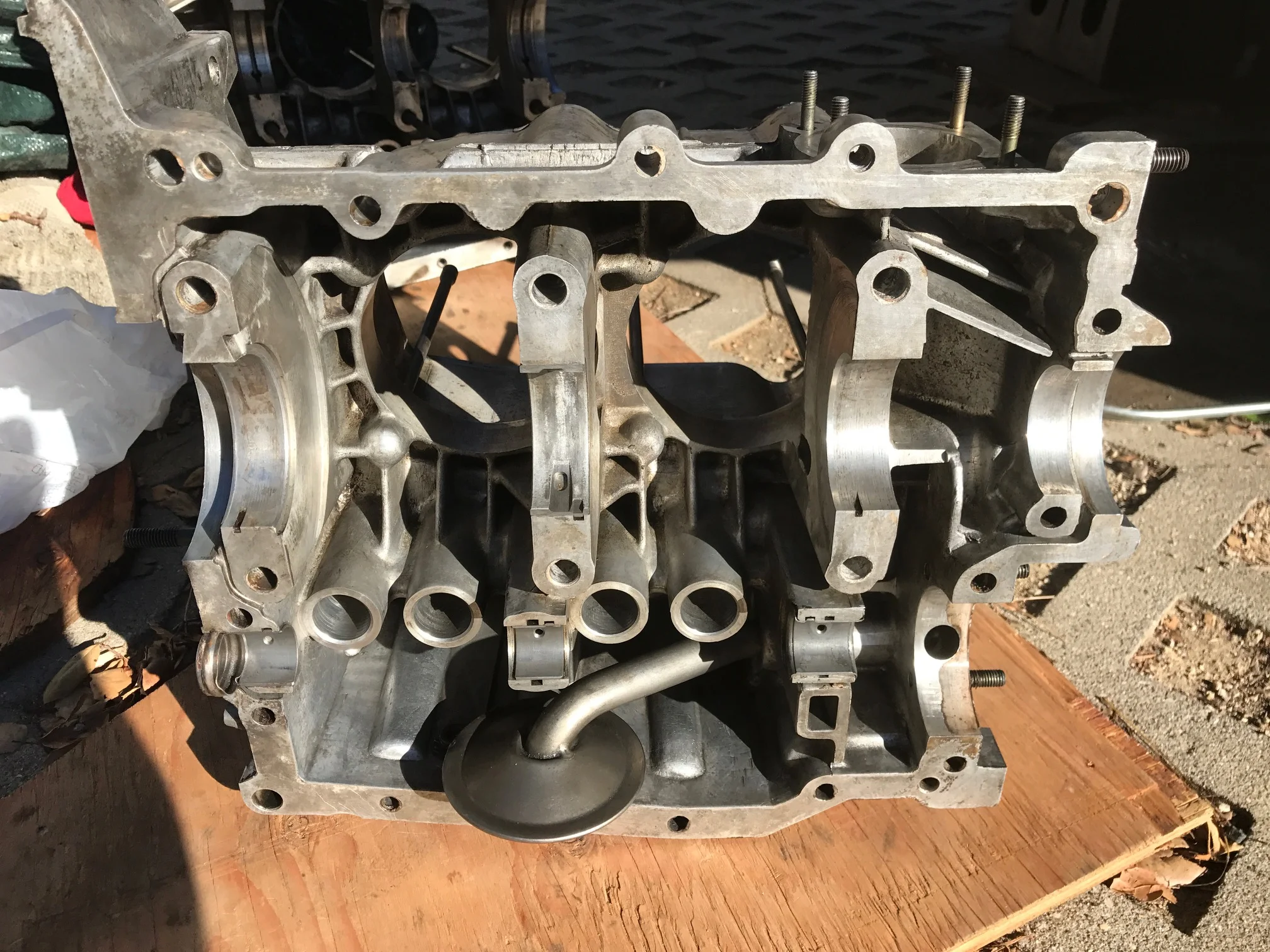
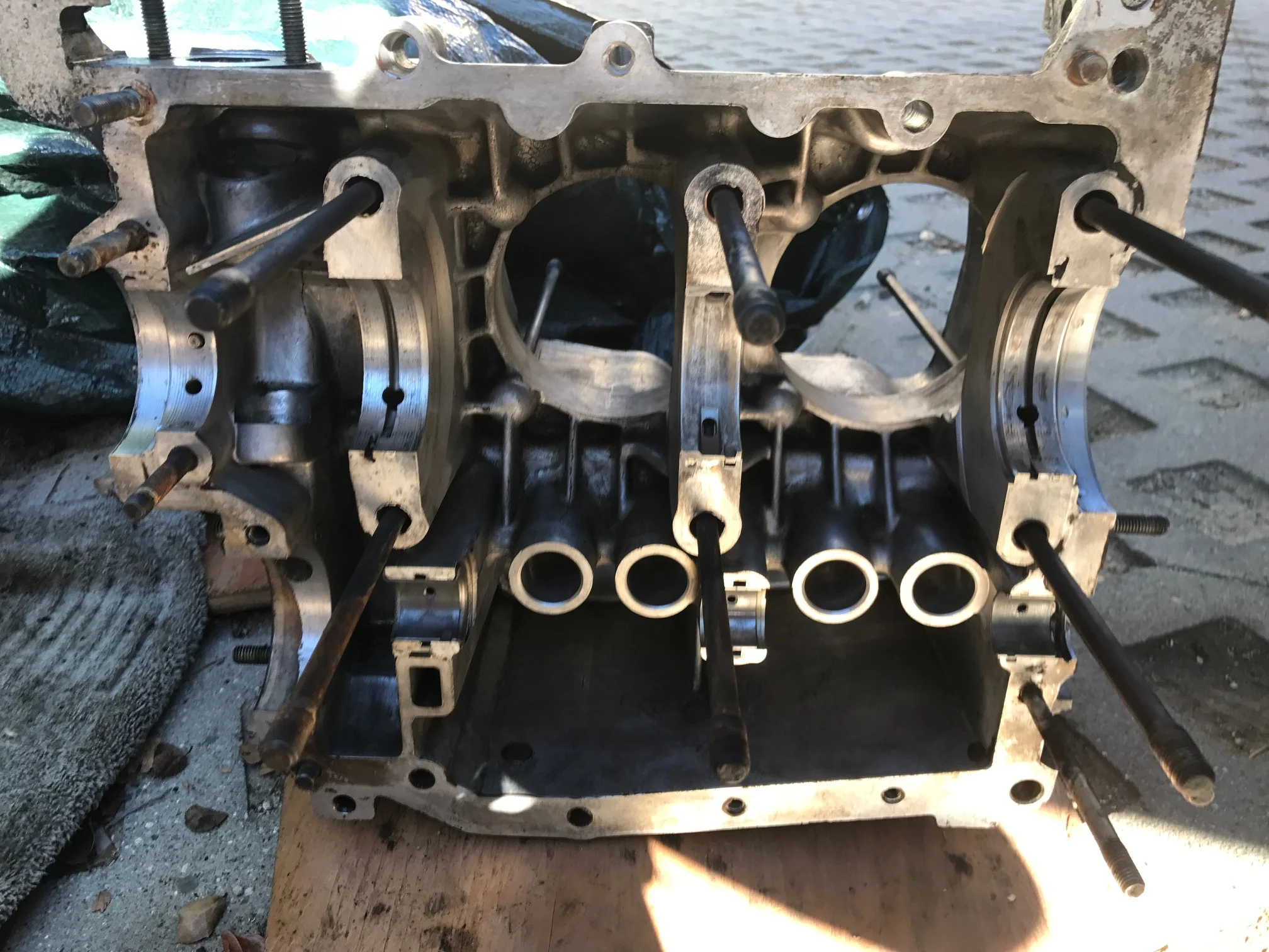
When I first saw Sue, she didn’t look very good. She was dusty, rusty, and musty. She didn’t run and I didn’t know a thing about working on cars. So it made perfect sense to buy her. After becoming a regular at Harbor Freight, Autozone, and O’Reilly’s, she was finally up and running.


After the engine was all fixed I tuned the brakes, cleaned the fuel tank, replaced the radiator, and cleaned up the wiring. Once she was mobile, Riley and I knew we had to take her on a roadtrip. This meant two things: install a kitchen, and wire in auxiliary power.
Kitchen
Early on, we knew we didn’t want to do the cooking inside - it’s too cramped. So a built-in stove wasn’t necessary. We did need food storage space, food prep space, and a sink to wash the dishes. We also knew how much space we had to work with. The cabinet we wanted to build had to fit between the bed and the front seat, sit below the window, and couldn’t be too deep. We built a frame to those specs first. We decided water storage capacity was higher priority than food storage - you can go much longer without food than water. The water storage tanks had to fit in to a Sparkletts vending machine for ease of refilling and had to be light enough when full to be carried by hand. After searching online, we found 7-gallon freshwater storage tanks that best fit our needs - one for freshwater and one for gray water (we didn’t have a good guess for ratio of consumed water to gray water so sized them the same). Deciding how to pump to the faucet was mostly a financial decision between a manual pump and an electric one, but it didn’t cost out as expected. An electric pump was 1/3 the cost of a manual footpump! This did have some important ramifications though, if our batteries went dead we’d have no use of our sink. A nice part about the electric pump was it’s small footprint. It fit perfectly in a gap between the two tanks. With our water compartment size now known, we knew how much space was left for the food storage. We decided to use low-walled drawers instead of shelves again because of the cramped space - it’d be hard to bend down and see what’s stored away. We chose a sink to fit neatly over the water compartment, while still leaving room for food prep space.
Another cool feature we built in was a stowable table. When not in use, the table could be stowed over the counter surface. Then when needed it could be rotated away from the countertop and lowered to a comfortable level when sitting on the bench. It was attached to the side of the cabinet by inserting the table’s pipe into a PVC pipe of slightly larger diameter. This more than doubled the amount of prep space and added a convenient “indoor“ place to eat.
Once our entire kitchen had been put together, we bolted it in place.
Auxiliary Power
Auxiliary power was important. We needed to be able to charge our devices (phones, laptops, camera, etc.), run the sink pump, and power peripherals like fans without discharging the starter battery. We decided on a 12V system because the pump was 12V and most auto accessories run on 12V. The next step was to estimate our daily energy consumption. Knowing this, we had to make estimates about the amount of sunlight per day and the number of consecutive days without sunlight we could expect. We also had to find the max power draw. The largest power draw would be ~300 watts charging both of our laptops at the same time. With all this info, we derived our battery, inverter, and solar panel minimum requirements.
We had three basic locations to pick from to put the system. There was space under the driver’s seat, under the rear bench, and in a cubby in the engine compartment. The underseat location was great because it wasn’t utilized for anything else and kept everything out of sight. The drawbacks were that it was a long wire run from the rooftop solar panel and there wasn’t any easy waterproof wire entry location. The engine compartment had similar benefits - it was out of the way, the space was otherwise underutilized, but it also had the advantage that the wiring from the roof would be simple. The drawbacks were that it was inconvenient to access the cubby and the wiring runs from the system to the interior would be fairly long. The last location under the bench offered convenient access and easy wire entry. The drawback was that this space could easily be used for storage. After weighing the options, under the bench was clearly the winner. Now that we knew where we were putting everything, we could start putting it all together.
We found the battery and solar panel on Craigslist. We then purchased the charge controller, inverter, and a fuseblock online. The charge controller was selected for two reasons, MPPT to extract as much power as we could from the panel, and it had a low voltage cutoff output (which will come up later). Additionally, we installed a charging relay that connected the auxiliary battery to the starting battery. It wasn’t necessary, but gave us two important options. One was that we could charge the auxiliary battery with the engine, so in the chance our battery runs low and there’s no sun we can still charge our laptops (important because Riley works remotely). This ended up being really useful on the road. The other advantage was that if our starter battery died it could be charged by the auxiliary battery and solar panel. The rest of the wiring was relatively simple with one exception. Drawing down a battery’s voltage too low damages it, something the low voltage cutoff on the charge controller is able to protect against. Unfortunately, the charge controller was limited to 20A output, not even enough to run the inverter, and we still wanted to be able to use power in an emergency. To deal with this, we could wire in relays. The control circuit could run through the charge controller and the slave circuit could run from the battery to the load. Except this would still leave us with no power in an emergency if we had a low battery. To solve this we wired in an On/Off/On DPDT switch, with the common terminal wired to the relay control circuit, the upper terminal wired to the charge controller low voltage cutoff output, and the remaining terminal wired directly to the battery. This way with the switch up power was available as long as the battery had a healthy voltage, with the switch in the middle power off, and with the switch down power available even with low voltage at the battery. Two of these circuits, one each for the fuseblock and inverter, and the wiring was finished. Where possible, we used circuit breakers instead of fuses for circuit protection. This way, closing the circuit would be simpler than having to bring along or buy replacement fuses. They also made it so we could easily open and close certain circuits by manually tripping the breakers, making any ongoing work much quicker. As an extra layer of circuit protection, we ran longer runs of hot wires through conduit to prevent any fraying and grounding.
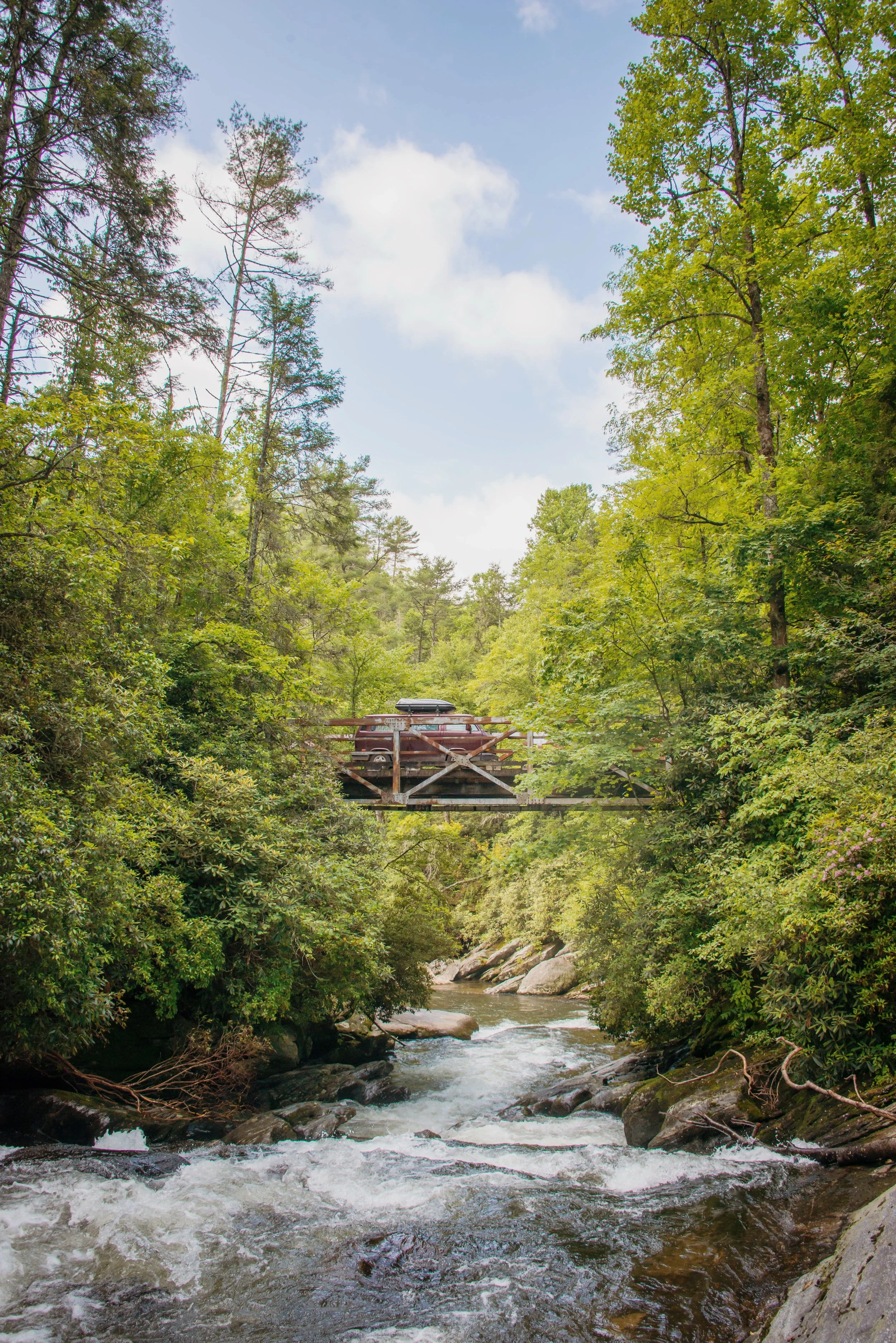
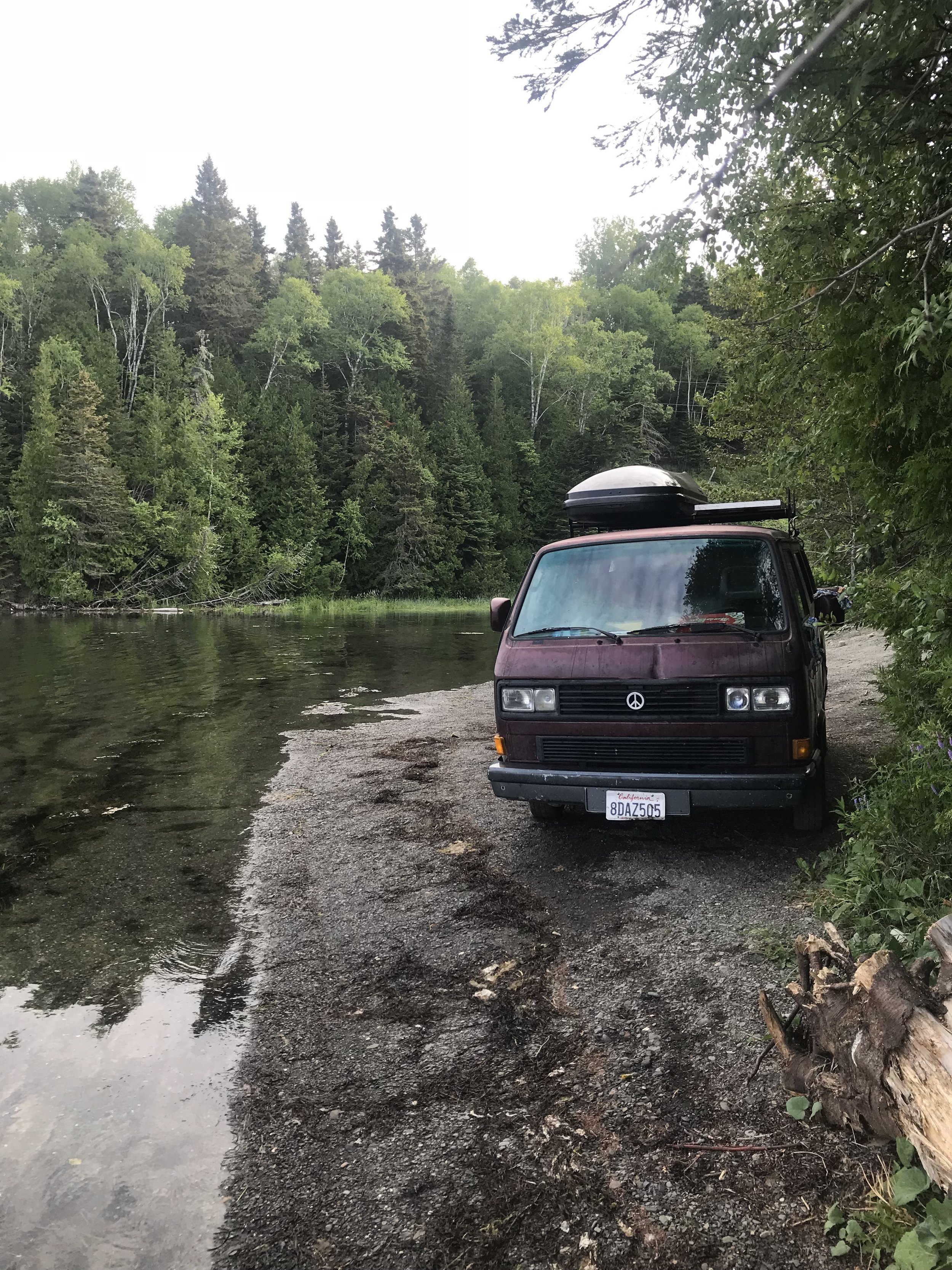
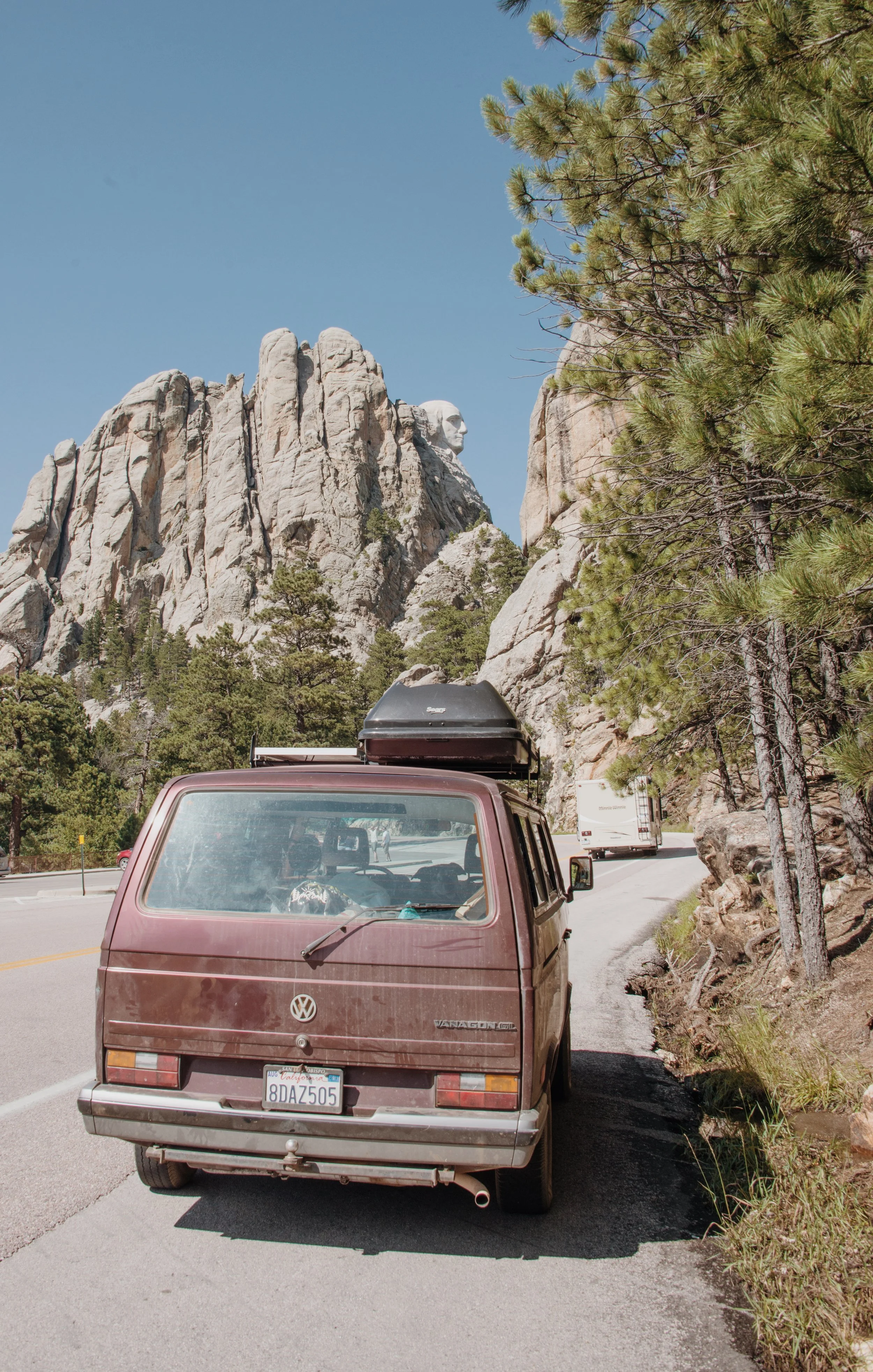
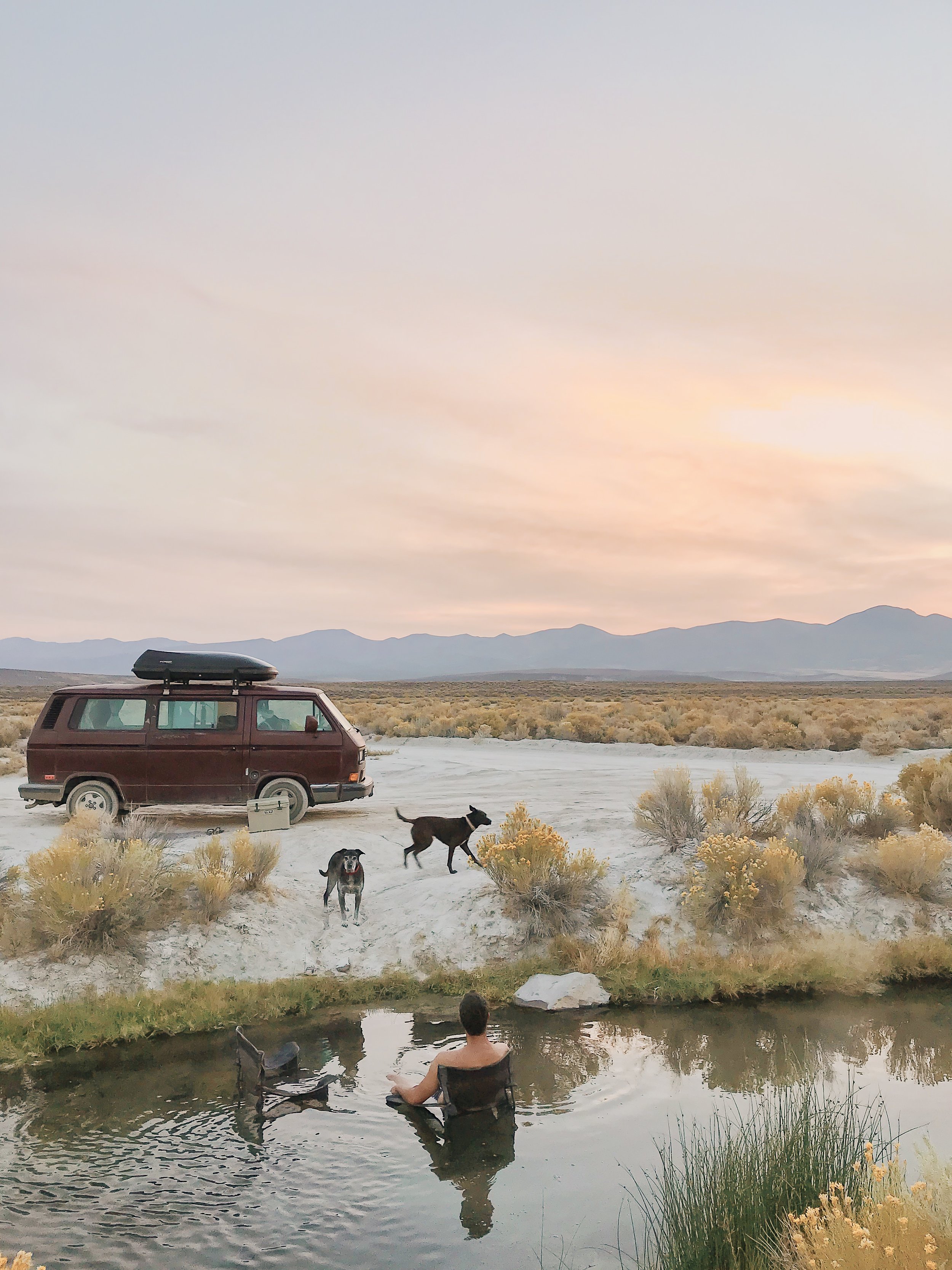
Road Trip
Once everything was ready to go, it was time to hit the road. Over 4 months we traveled 24,000 miles through 43 states and 4 Canadian provinces. I’d write more about it but that would be a full book’s worth, so instead I’ll just leave some pictures.